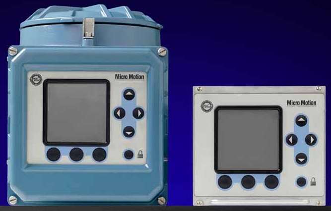
Model 1700 or Model 2700 Transmitter Safety Manual for SIS. Micro Motion sensor installation manuals Documents generated by Micro Motion. 4 Coriolis Flowmeter with Model 1700 or Model 2700 Transmitter Micro Motion Proof Test 1 The following proof test is recommended for all flowmeters. Watch this video to learn how the 8700 Series of magnetic flow meters can help you manage uncertainty with the help of our advanced flow measurement diagnostics, including Smart Meter Verification.
- Emerson Micro Motion Flow Meters
- Micro Motion Flow Meter Installation Manual
- Micro Motion Cmf025 Manual
- Micro Motion Manual
- Micro Motion Flow Meter Manual
Installation Manual 20002158, Rev DI March 2014 Micro Motion® ELITE® Coriolis Flow and Density Sensors. The Micro Motion F-Series Coriolis flow sensor measures necessary flow and density process variables simultaneously with reliable performance, even under the most demanding of process conditions. Multiple line sizes provide an ideal platform for batching, distribution, allocation and intra-plant measurement applications.
Local display (standard)
Table 10-7:
2 Micro Motion® Model 1700 and 2700 Transmitters Before You Begin 1.3 Flowmeter components The Model 1700 or 2700 transmitter is one component in your Micro Motion flowmeter. Other major components include:.The sensor, which provides measurement functions.The core processor, which provides memory and processing functions. Wire the meter according to the recommended practices for Chapter 3 your process environment and required approvals. Select the control pressure for the meter. See Micro Motion Specific Gravi‐ ty Meters (SGM): Configuration Purge cycle the meter. And Use Manual Calibrate the meter. Micro Motion will not accept your returned equipment if you fail to follow Micro Motion procedures. Return procedures and forms are available on our web support site at www.emerson.com, or by phoning the Micro Motion Customer Service department. Emerson Flow customer service Email:. Worldwide: flow.support@emerson.com.
Type
Description
Local display
Standard user interface with 2-line LCD panel
•
Two optical switches for local operation
•
Glass or plastic lens options
Local interface functions
Segmented 2-line display with LCD screen with optical controls
and flowmeter-status LED is standard.
•

Suitable for hazardous area installation.
•
Available in both backlit and non-backlit versions.
•
Available in non-glass or non-glare tempered glass lens ver-
sions
•
Can be rotated on transmitter, 360 degrees, in 90-degree in-
crements.
•
Supports English, French, German, and Spanish languages.
•
View process variables; start, stop, and reset totalizers; view
and acknowledge alarms.
•
Zero flowmeter, Smart Meter Verification, simulate outputs,
change measurement units, configure outputs, and set RS-
485 communications options.
•
Emerson Micro Motion Flow Meters
Three-color LED status light on display panel indicates flow-
meter condition at a glance.
Local display optimized for Chinese-language support (China only)
Table 10-8:
Type
Description

Local display optimized for Chi-
nese-language support
Graphical user interface with 6-line LCD panel
•

Three optical switches for local operation
•
Glass lens only
•
For purchase in China only
Local interface functions
Segmented 6-line graphical display with LCD screen with optical
controls and flowmeter-status LED is standard.
•
Suitable for hazardous area installation.
•
Available in both backlit and non-backlit versions.
•
Available in glass lens version.
•
Can be rotated on transmitter, 360 degrees, in 90-degree in-
crements.
•
Supports English and Chinese languages.
•
View process variables; start, stop, and reset totalizers; view
and acknowledge alarms.
•
Zero flowmeter, Smart Meter Verification, simulate outputs,
change measurement units, configure outputs, and set RS-
485 communications options.
•
Three-color LED status light on display panel indicates flow-
meter condition at a glance.
Micro Motion Flow Meter Installation Manual
Specifications
112
Micro Motion
®
Model 1700 and 2700